UPDATE! Previously I have used Arduino with CNCshield as electronics just as I mention in the video. The software Estlcam has stopped supporting that electronics so you have to go back to version 10 if you want to be able to use that electronics. Another alternative is to use Arduino Mega260 see video example here: https://youtu.be/DFU-zd2rKJA?si=qeX8bjQSb7qmBbE6. CNC electronics is a jungle and there are countless of alternatives…
If you use Arduino as electronics, you can only use GRBL based software, i.e. everything that controls Arduino. There are tons of options and choose something that can interpret the Arduino UNO 3.0 (which applies to most)
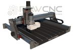
Quick Facts Arduino
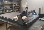
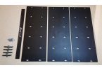
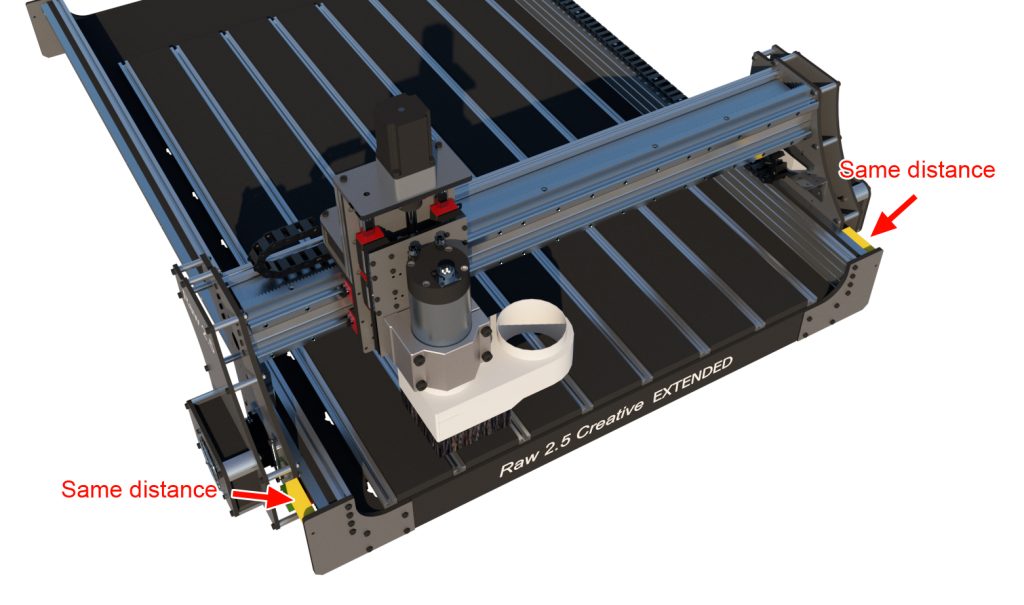
Arduino has some limitations compared to industrial electronics but it is getting better and better. As an example, we lack the ability to calibrate the machine 90 degrees. If you use industrial electronics, you can drive the machine home, the left and right position switches can be controlled individually so that the machine can end up 90 degrees, Arduino electronics currently lack this so you have to set the machine 90 degrees manually. To do this, you can cut out 2 blocks of exactly the same length, e.g. 7cm long. Clamp them between the corner plate and the side plate on both sides and press the entire axis against the blocks, start the electrical box and the machine will lock itself 90 degrees until you switch off the machine. See image below.
Advantages of Arduino are that the software is cheap and works well for normal use.
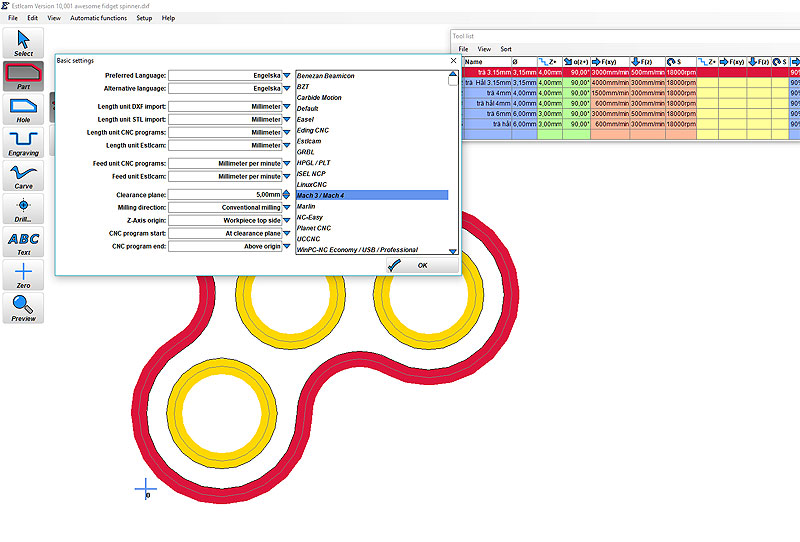
Set up Estlcam Software (version 10 and below the latest versions don’t work with Arduino UNO)
We recommend using Estlcam to control the machine. Estlcam can both cut flat files and also 3D, which is unique for such an inexpensive program. Here is an example of how to install Estlcam with your electronics
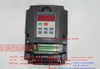
Note, some Windows computers, cant find the comport, if that is the case then you need to install a new driver. Search on Google for “Arduino ch340g driver” or go directly to Arduino homepage and download the drivers.
We will use Estlcam but you can use any software compatible with arduino. Go here to see whats avalible https://github.com/grbl/grbl/wiki/Using-Grbl Or search for Grbl software.

Note, some Windows computers, cant find the comport, if that is the case then you need to install a new driver. Search on Google for “Arduino ch340g driver” or go directly to Arduino homepage and download the drivers.
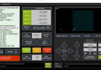
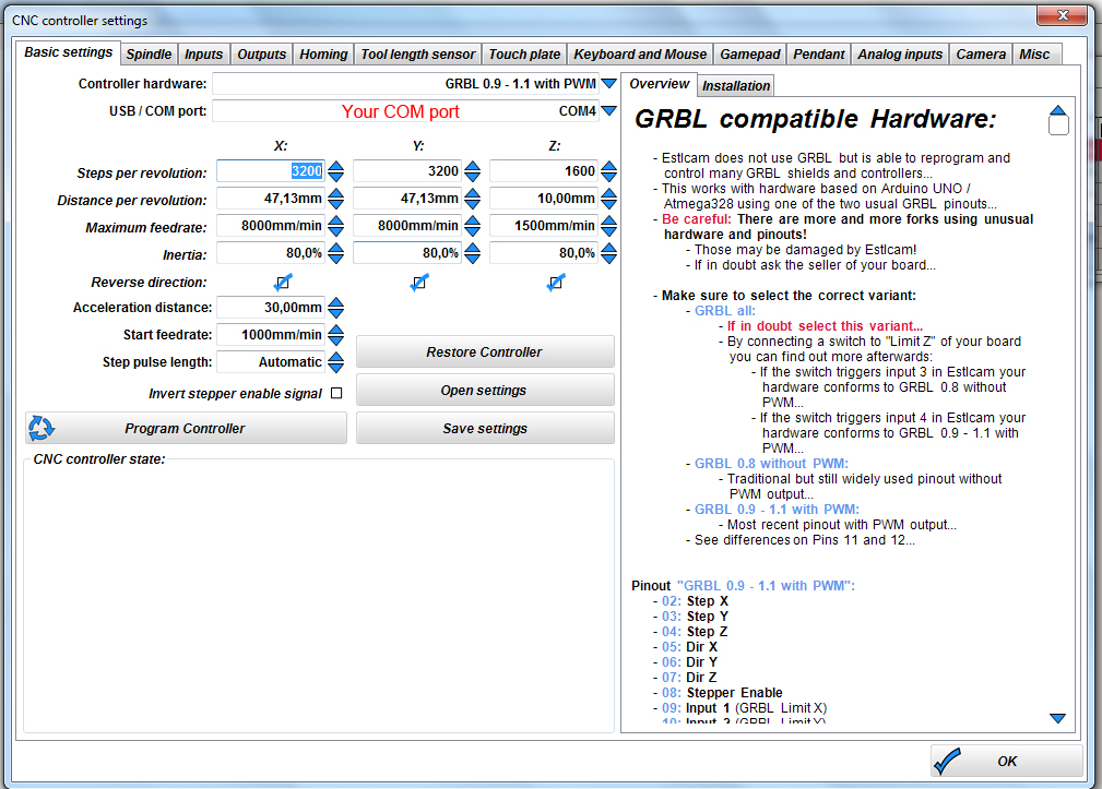
Copy the values in the image below. Note, the distance per revolution value may be different for you depending on which timing belt pulley you choose, i.e. how many teeth it has. In the video I use HTDM5 timing belt pulley with 15 teeth. To calculate the distance I can take the number of teeth times the Pitch (distance between teeth) which is 5mm on an HTD M5 belt (3mm on an HTD M3 belt) I then fill in 75.00mm for X and Y axis.
Z-axis has lead screw with a Pitch of 3mm so I fill in 3.00mm.
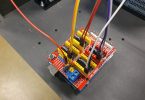
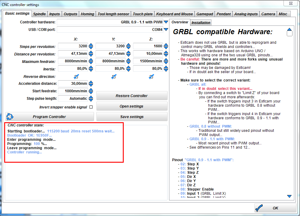
If all goes well, the Arduino board will be programmed with our information and it should look like this…
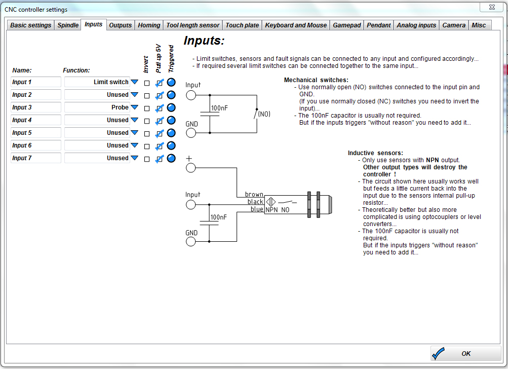
If you are adding limit switches, you can copy the image below but also have your own settings
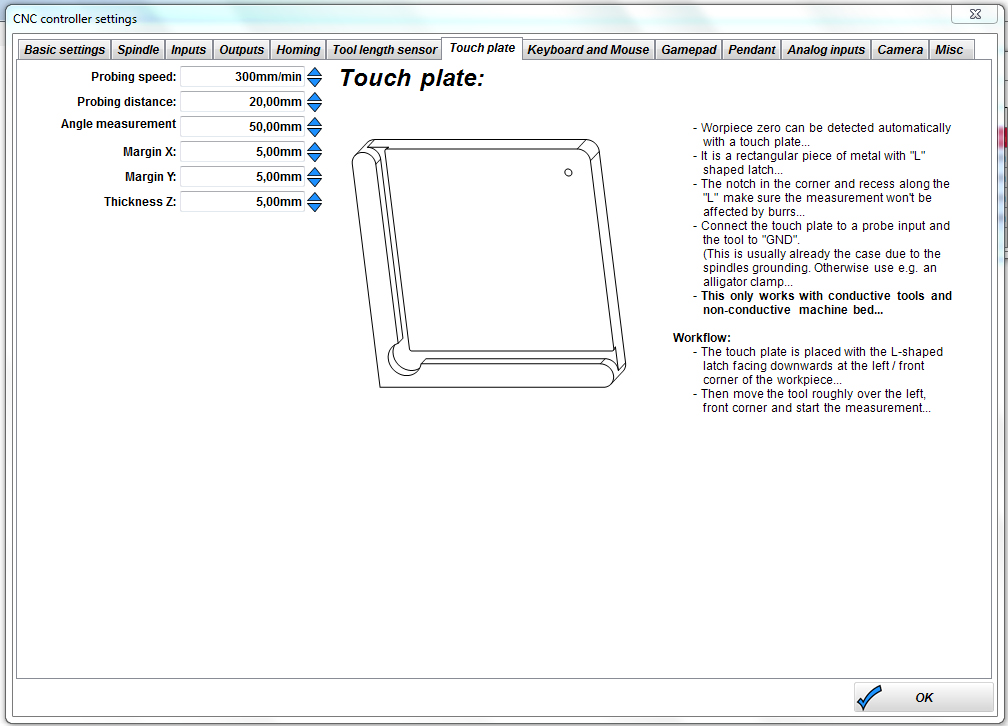
If you want to use a calibration plate or elevation plate, you can copy the values below, but change them to suit you.
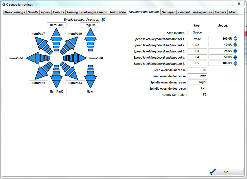
If you want to control the machine with the keyboard, you can do as below.
We are done!
Go to YouTube and search for Estlcam tutorials to get started, it’s easy after you create your first file